Roblox introduced Constructive Solid Geometry back in 2014, and supporting the physics simulation of this project was my first large project on the simulation team along with Tim Loduha. Back then the company was much smaller, and the Physics team only had two people who had other non-development responsibilities. So, in the spirit of fast results, we went to a very popular library called Bullet Physics for help. Bullet Physics is used in many games today because of its accessibility and feature-richness, and its open-source nature and extendability made it the natural choice for Roblox’s needs.
While the Roblox physics engine is built in-house, there were two primary components we needed to use from Bullet Physics to make PartOperations work in simulations:
-
- Complex Geometry collision detection
- Convex Decomposition to generate a collection of convex objects for collision detection of arbitrary 3D geometry (standard in the industry due to solution space and performance constraints)
When we were originally working on the Convex Decomposition portion of the project, we experimented with two Algorithms that came with BulletPhysics:
- Hierarchical Approximate Convex Decomposition (HACD)
- Approximate Convex Decomposition (ACD)
While we liked the results of HACD, the robustness and consistency of ACD won us over for the initial product ship.
Precision Feedback
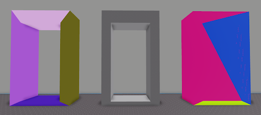
After the feature shipped, we amassed a mountain of feedback where users were expecting better geometric results from collision detection. ACD’s use of coarse voxelization caused various artifacts, such as important surfaces from doorways or ledges being displaced or covered.
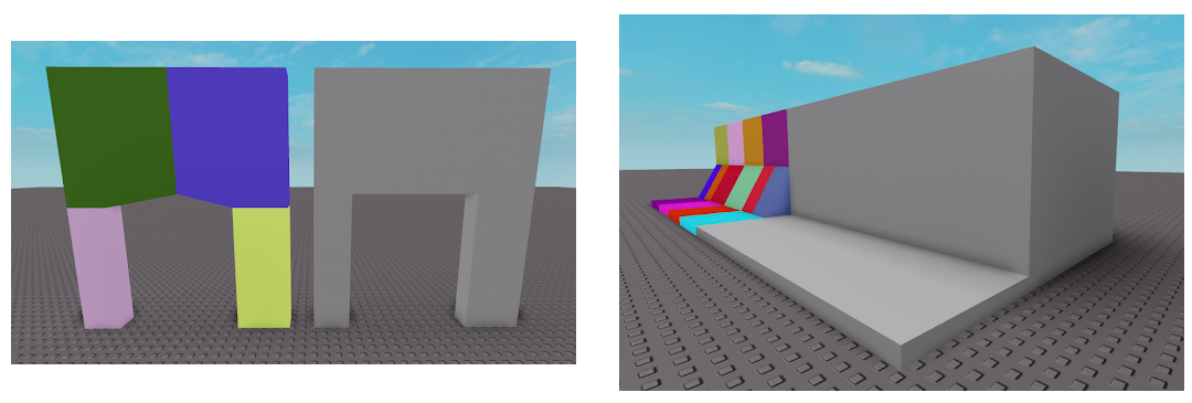
You can imagine how these concavities were sealed by imagining how a complex shape would be viewed through the eyes of a voxelizer (below).
We needed something better – something that respected the original geometry. Voxelization was out of the picture due to how surfaces tend to “snap” to voxel grids. We needed something that would automatically work in the vast majority of input geometries without any manual correction.
Hierarchical Approximate Convex Decomposition
We eventually came back to HACD due to the following qualities:
- The input mesh was used as the initial state of the algorithm
- Error-checked against original input geometry
- Handled non-manifold (so did ACD)
- No voxelization
Based on the paper linked above, HACD has 3 primary components:
- Dual-Graph Elimination
- Convex Hull Generation
- Concavity Error Calculation
Algorithm Overview:
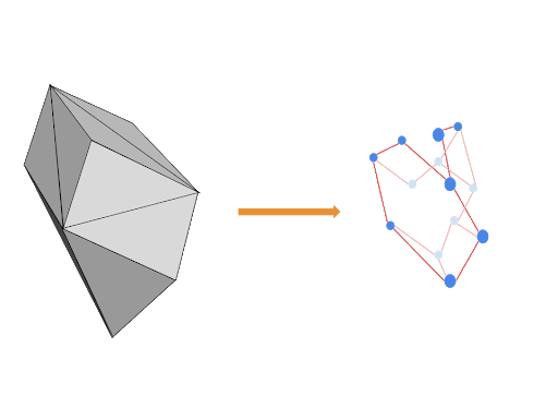
1. Input mesh is taken and turned into a graph where each triangle is a node and each edge between two triangles is an edge in the graph. This is the starting dual-graph, where each triangle is treated as an initial convex hull.
2. We go through every edge in the graph and calculate the predicted convex hull that would result from combining the convex hulls of the nodes the edge connects.

3. We use this predicted convex hull to then calculate the concavity error incurred by the original geometry. These errors are used to sort all the edges in the graph from least erroneous to most.
4. Finally, we take the edge with the smallest error.
a. If the error is less than the configured max allowed concavity error we remove the edge (edge-collapse) and replace the two nodes with the edge’s predicted convex hull.
b. If the error is more than the configured max allowed concavity error we terminate.
5. Every time an edge is removed by edge-collapse, this invalidates the previous concavity error results for adjacent edges, so we repeat steps #2 and #3 for adjacent edges.
6. We update the re-calculated edges in our sorted edge list based on the new concavity errors.
7. Repeat Steps 4 through 6 until the only edges remaining have error values greater than global allowed error (this is configured by the user before starting the algorithm).
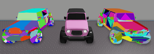
We grabbed the latest available version of open source HACD code and tested it on some meshes. Some shapes, like the car, resulted in a more improved collision geometry than we’ve had before, but other input meshes resulted in questionable outputs. The algorithm in theory seemed fine, so our next step was to figure out what was causing these strange results.
Visual Debugging
Since we didn’t know the implementation’s internal operations well, we did the only thing we could to speed up our investigation. We wrote a visual debugger that would record every step of the dual-graph edge removal process and allow us to step through every change to the original geometry one step at a time.
With this tool we were able to identify that there were issues in both the concavity error calculation and the convex hull generation. We were able to step through and find cases where a correctly formed convex hull would have blocked an important and large concavity, yet the concavity error calculation would report the edge-collapse that formed this hull as having no error at all. On the convex hull generation side, we found that edge-collapses would sometimes cause vertices and entire faces to go missing. This would result in minor surfaces missing in some cases, and complete devastation in others.
And with that, we recognized that we had to dive deep and write our own logic for each of these components.
Concavity Error Calculation (Step 3 from Algorithm Overview)
The purpose of concavity error calculation is to quantify the amount of “damage” to the original geometry a removal of an edge would cause by its creation of a new convex hull by combining the hulls the edge connects. The original paper mentions that this error can be tracked many ways, and the implementation used the farthest distance from the original surface to the newly formed surface within the newly formed predictive convex hull. We will use the same definition.
 To acquire this quantity we need two pieces of information:
- Some quantifiable representation of the source geometry
- The predictive convex hull that would form from the removal of this edge (Step 2 from overview).
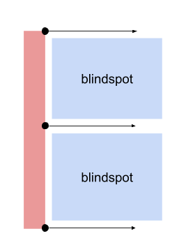
The original HACD implementation used a few sample points per triangle as a representation of the original surface (During Step 1 from overview). These points would then be used to raycast from, along the face normals, to find the backface of a convex hull that is impeding concavities. The longest distance from the original surface to the backface was considered the error. This is a reasonable approach, but due to the sampling density being a per-triangle operation, we ran into issues where simple shapes with large triangular faces had massive blindspots when scanning for objects that may be blocking concavities.
 An ideal system would essentially attempt to do a surface extrusion from the original surface triangles onto the convex hull being tested, but this is a very expensive problem to resolve and optimize, so instead we will aim to sample original triangle surfaces but with a more consistent distribution.
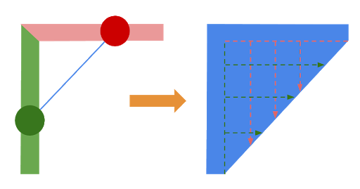
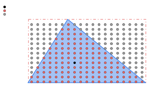
We will uniformly generate surface sample points for every triangle based on a configured grid distance (see left). Since this will generate a large amount of points, we also need a way to quickly filter which points need to be checked against newly forming convex hulls during the concavity error calculation process. To accomplish this we toss every sample point into a spatial grid, similar to ones used in collision detection, using the bounding box of a hull that we are testing to quickly select a group of surface sample points to test against.

Once we grab the points we find to be inside the bounding box, we further filter for points that are INSIDE the newly formed convex hull, since we are trying to catch concavities sealed by the current convex hull. We then raycast from these sample points against the triangles of the hull. If there is no error added, all will return distances of zero, but a problematic convex hull, like in the above diagram, will have the raycasts from the original surface impact the backface of one of the predictive convex hull‘s triangles!
In summary, the error generation can be described as such:
- (During step 1 from algorithm overview) Uniformly sample points on each triangle and toss them into a spatial grid.
- Grab the bounding box of the convex hull we are testing and gather all points in the grid inside of this bounding box.
- From the gathered points, for every sample point INSIDE the convex hull, we do a raycast along the original surface normal to see if it hits the backface of the convex hull.
- The ray with the largest distance that hit a backface ends up being our concavity error.
- If the convex hull does not extrude outside of the original surface, the result should be 0.
- This can be optimized by exiting early as soon as the first sample raycast exceeds the maximum allowed global error, as this is enough to stop an edge from collapsing.
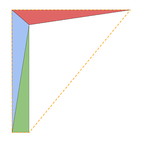 This system provides us with a robust way of checking convex hulls for how much error they would introduce to our original shape, but there is one thing still missing. This method only works well on 3D convex hulls. If the convex hull is flat, the sample points would never be aligned in the directions we would need to test during the formation of 2D convex hulls. Take for example the configuration on the right, if the blue and green triangle form a convex hull and then attempt to combine with the red, any sample points inside of this convex hull would most likely not impact the backface of the convex hull at any distance but 0. In order to properly resolve this, we would have to consider a completely different 2D error calculation process, which would be just as involved as the one we described.
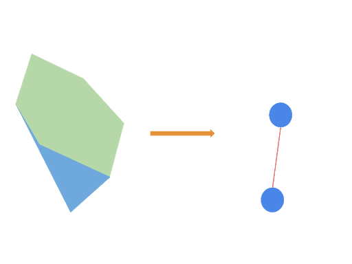
There is a small trick we can do instead. We can compare the area of the sum of the original two convex hulls to the area of the result. If the resulting hull has more area than the sum of the two source hulls, you know it may be closing a concavity, and therefore the square root of the extra area can be treated as the concavity error in this case! And finally, we have a good method to detect errors in potential convex hull candidates, provided that our input convex hulls are properly formed!
Convex Hull Generation: Quickhull (Step 2 from Algorithm Overview)
After tweaking the concavity error calculation, we used the visual debugger to confirm that we still had issues:
- Certain convex hulls that would seal large concavities would still pass the concavity error test with a result of 0.
- Combining two convex hulls would sometimes cause a vertex to disappear, leaving a hole in the original shape.
The original implementation of HACD used a variant of the Quickhull algorithm, which is a perfect choice because the algorithm is designed to quickly add new points to an existing convex hull, which we will be doing as we collapse edges. An initial review of data collected by our visualizing debugger revealed that occasionally the resulting hulls would have an inverted triangle, which was a showstopper for our previously described concavity error calculation method.
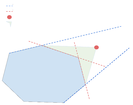 The way this algorithm is supposed to work is that when you pick a new point to add to an existing hull you then find triangles for whose planes the point lies outside. These triangles are then marked for deletion, while their edges to other triangles will be used to form a new set of triangles with the point being processed to seal the convex hull. Something you can learn from Valve’s talk about the Quickhull algorithm is that it is very sensitive to floating point errors, especially if one of the hulls has coplanar triangles. The example on the right is a cross-section of the easy case that does not illustrate the problem described by Valve.
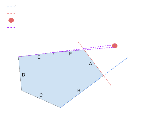 To understand the problem you have to consider a cross section that looks like the shape on the left. Consider a Quickhull situation where we’re not quite sure whether triangle E and F consider the point outside or inside their planes. In fact the worst case scenario is where E considers the point outside, while F considered the point inside. In Quickhull, because triangle orientation depends on adjacent triangles, this kind of inconsistent topology can either create poorly oriented triangles, or result in a complete failure.
Dirk Gregorius at Valve deals with this problem by merging coplanar triangles into singular face objects such that this kind of inconsistency is impossible, however we cannot use this approach as the distinction between individual triangles is still important to us. Instead we create a thick plane that multiple coplanar triangles belong to and use this plane to make sure that any triangles that are connected together and fit within the plane can only resolve the calculation for whether a point lies inside or outside in a singular way. This essentially resolves the problem in a similar way that Dirk’s face-merge solution does, while letting us maintain direct references to individual triangles.
As before with concavity error calculation, we must consider the 2D case as well. In order to protect your Convex Decomposition code from a variety of input data, you MUST implement a 2D Quickhull AS WELL as a 3D Quickhull to allow the combination of coplanar triangles. If we attempt to use the same process for coplanar triangles, it will not work and often delete input vertices or fail.
Consistent Floating Point Treatment
After coming up with solutions for convex hull generation and concavity error that we trusted and we understood, we were still running into some issues, but visual debugging revealed that it was usually in the cases of semi-degenerate surfaces.
This brings us to one of the most important concerns in 3D geometry – consistent treatment of floating points is a must. In order to make this algorithm work robustly, the concept of epsilons and quantized information had to be unified.
Throughout the algorithm there are various points where a concept of epsilon was used:
- When creating a dual-graph from input geometry, degenerate vertices were combined into a single vertex.
- Throughout convex hull generation we needed to test whether convex hulls were coplanar with each other, to decide whether we had to operate in 2D or 3D mode.
- During concavity error computation, we also needed to test the current hull for flatness, and needed consistent epsilons for raycasting against the interiors of convex hulls.
Once quantization distance (s) is determined as a configuration of the algorithm we must treat that s as the epsilon, and also our definition of flatness. This means that all points that fit within a single plane of width s must be considered coplanar. Any convex hull generation on a set of points that fit in a plane width s must be treated as purely 2D operations. Furthermore, all of our queries about epsilons must be done in a single dimension, meaning that any inquiries for volume, or area of objects must be checked against maximum distances from a plane.
Conclusions
At the end of the process it is always fun to take a step back and ask “What did we learn?” For HACD we would definitely highlight the importance of the following high level concepts in order to achieve consistent quality results:
- Uniform surface sampling – we need a good fair view of the original geometry gauge how well the algorithm is progressing.
- Distinction between 2D and 3D operations during concavity error calculation, and convex hull generation – the algorithm spends a significant portion of its time dealing with 2D operations unless your input geometry smooth objects with no coplanar faces. The 2D phase of the algorithm is extremely important.
- Consistent system for quantization and floating point treatment – crucial for calculating connectivity of input triangles, helping with Quickhull coplanar face problem, and splitting 2D and 3D operations.
These three concepts are the fundamental pillars that lead our massive internal refactor of the HACD library, and allows us to ship it as a generic automatic collision geometry generator for Roblox’s triangle mesh and CSG objects. Even with this work done, there is a significant amount of work ahead of us to make this system even better.
There are various avenues for research we would like to follow with this method:
- Parallelism, performance improvements.
- Volumetric conservation: Our current algorithm does not conserve volume, which is something that VHACD focuses on solving.
- Improved 2D concavity error: Our current 2D concavity error calculation gives false positives since we are checking for a change in area as opposed to closure of concavity. This could be a problem because blocking edge-collapse unnecessarily removes a potentially valid solution from the convergence of your algorithm.
- Exposing algorithm tuning to advanced users for fine-tuning results.
Roblox has always valued features that work by default, and being able to achieve high-quality collisions without manually massaging collision geometry is a difficult goal that we consistently strive toward. While we haven’t reached pixel-perfect collisions, we’re ecstatic to be able to simulate the results of difficult CSG operations automatically. This is only the first step in the exciting new phase of improving collision generation for arbitrary geometry in Roblox, and we’re excited to see where the team’s research and user feedback pushes our efforts next!
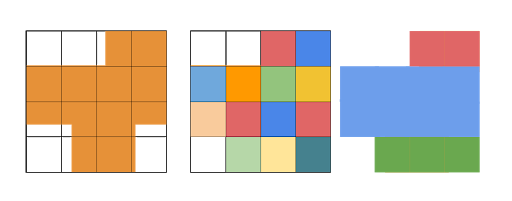
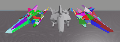
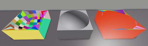
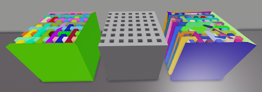
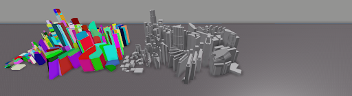
Results
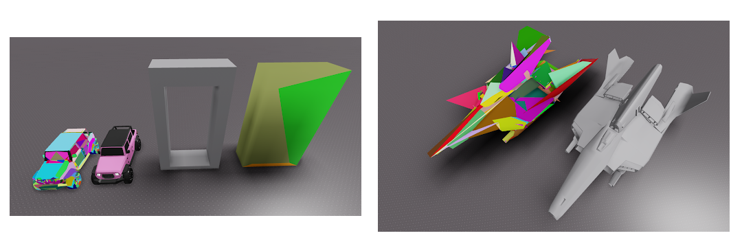
All of these results were calculated with consistent settings on original HACD and the Roblox HACD. Each color is a different convex hull.
SetNClusters 1
ScaleFactor 1000 // All objects get rescaled to a cube of 1000 x 1000 x 1000 for the operation
ConnectDist 0.1 // this is quantization distance
Concavity 10 // this is the allowed concavity error for edge-removal
CompacityWeight 0 // this setting favors edge collapse order based on perimeter, we do not use.
VolumeWeight 0 // this setting favors edge collapse order based on volume, we do not use.
Left: RoHACD Middle: Input Geom Right: HACD
Neither Roblox Corporation nor this blog endorses or supports any company or service. Also, no guarantees or promises are made regarding the accuracy, reliability or completeness of the information contained in this blog.
This blog post was originally published on the Roblox Tech Blog.